- 您现在的位置:买卖IC网 > Sheet目录1194 > ADM00333 (Microchip Technology)BOARD EVAL FOR PIC18F87J72
�� �
�
�PIC18F87J72� Evaluation� Board� User’s� Guide�
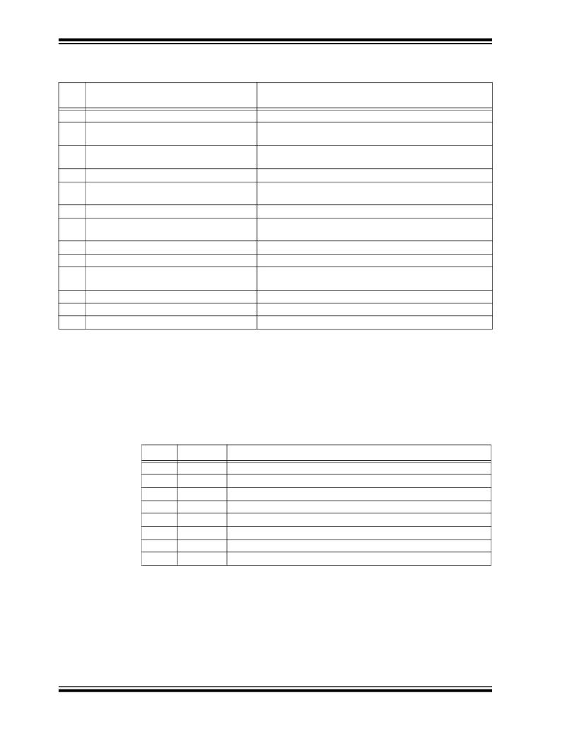
�TABLE� 2-1:�
�BOARD� LAYOUT� AND� COMPONENTS�
�SI�
�NO�
�1�
�2�
�3�
�4�
�5�
�6�
�7�
�8�
�9�
�10�
�11�
�12�
�13�
�Section� or� Component�
�PIC18F87J72� microcontroller�
�Seven� segment� LCD�
�High� voltage� section� with� connectors�
�RJ11� connector�
�Load� Cell� connector�
�PICtail� ?� connector�
�Touch� sensitive� keys�
�9V� battery� connector�
�MCP2200� –� USB� to� UART� serial� converter�
�Mini� B� USB� receptacle�
�9V� power� supply� jack�
�32.768� kHz� crystal�
�10� MHz� crystal�
�Functionality�
�Main� controller� for� all� functions� on� the� board�
�To� display� time� and� other� configuration� features� like� OSR,�
�Gain,� Bit� Width�
�For� connecting� universal� input� voltage� to� the� board� (when� not�
�using� 9V� supply� or� battery)�
�For� debugging� and� programming� purpose�
�Optional� provision� to� connect� an� external� load� cell� output� to� the�
�ADC� input� channels�
�To� connect� to� other� application-specific� daughter� cards�
�Touch� sense� switches� for� changing� configuration� of�
�Sigma-Delta� ADC�
�To� connect� a� 9V� battery� when� powering� the� board� through� it�
�To� communicate� with� the� GUI�
�To� connect� the� USB� port� of� the� computer� to� the� evaluation�
�board�
�9V� power� supply� to� the� board�
�Clock� to� the� internal� Real-Time� Clock� and� Calendar� (RTCC)�
�External� Clock� to� the� main� controller�
�2.1.1�
�PIC18F87J72� Evaluation� Board� Jumper� Settings�
��By� connecting� the� jumper� pins� appropriately,� different� configurations� can� be� achieved�
�on� the� board.� Care� must� be� taken� regarding� the� voltage� level� before� placing� these�
�jumpers.� Further� sections� in� this� document� describe� what� precautions� need� to� be�
�ensured� while� connecting� these� jumpers.�
�TABLE� 2-2:�
�JUMPERS� ON� THE� EVALUATION� BOARD�
�DS51990A-page� 12�
�SI� NO�
�1�
�2�
�3�
�4�
�5�
�6�
�7�
�8�
�Device�
�JP1�
�JP2�
�JP3�
�JP4�
�JP5�
�JP6�
�JP7�
�JP8�
�Description�
�Selection� between� high� voltage� and� low� voltage� input� on� channel� CH0�
�To� ground� Pin� 1� of� J4�
�Used� for� burden� connections� when� CT� output� is� connected� to� J4�
�To� ground� Pin� 3� of� J4�
�To� ground� Pin� 1� of� J5�
�Used� for� burden� connections� when� CT� output� is� connected� to� J5�
�To� ground� Pin� 3� of� J5�
�Selection� between� high� voltage� and� low� voltage� input� on� channel� CH1�
�?� 2011� Microchip� Technology� Inc.�
�发布紧急采购,3分钟左右您将得到回复。
相关PDF资料
ADM00344
BOARD DEMO EVAL FOR RE46C190
ADM00345
BOARD DEMO 3PH BLDC CTLR MTD6505
ADM1026EBZEVB
BOARD EVAL FOR ADM1026
ADN8831-EVALZ
BOARD EVAL FOR ADN8831
ADP1043AFB100EVALZ
BOARD EVALUATION ADP1043A 100W
ADP1046-100-EVALZ
BOARD EVAL FOR ADP1046-100
ADP1048-600-EVALZ
BOARD EVAL ADP1048-600
ADP190CB-EVALZ
BOARD EVAL ADP190
相关代理商/技术参数
ADM00344
功能描述:电源管理IC开发工具 RE46C190 Demo Board RoHS:否 制造商:Maxim Integrated 产品:Evaluation Kits 类型:Battery Management 工具用于评估:MAX17710GB 输入电压: 输出电压:1.8 V
ADM00345
功能描述:电源管理IC开发工具 3-Phase BLDC Snsrlss Fan Cntrllr
RoHS:否 制造商:Maxim Integrated 产品:Evaluation Kits 类型:Battery Management 工具用于评估:MAX17710GB 输入电压: 输出电压:1.8 V
ADM00352
功能描述:电源管理IC开发工具 MCP16301 600mA Demo Board
RoHS:否 制造商:Maxim Integrated 产品:Evaluation Kits 类型:Battery Management 工具用于评估:MAX17710GB 输入电压: 输出电压:1.8 V
ADM00360
功能描述:电源管理IC开发工具 MCP16301 300mA D2PAK Footprint Demo Board
RoHS:否 制造商:Maxim Integrated 产品:Evaluation Kits 类型:Battery Management 工具用于评估:MAX17710GB 输入电压: 输出电压:1.8 V
ADM00375
功能描述:BOARD EVAL FOR MCP6H04 OP AMP RoHS:否 类别:编程器,开发系统 >> 评估板 - 运算放大器 系列:- 产品培训模块:Lead (SnPb) Finish for COTS
Obsolescence Mitigation Program 标准包装:1 系列:-
ADM00393
功能描述:电源管理IC开发工具 64KB Flash, 8KB RAM 16MIPS USBOTG Crypto RoHS:否 制造商:Exar 产品:Evaluation Boards 类型:DC/DC Converters, Regulators & Controllers 工具用于评估:XRP6670 输入电压:2.6 V to 5.5 V 输出电压:0.8 V to 5 V
ADM00397
制造商:Microchip Technology Inc 功能描述:MCP19111 EVALUATION BOARD - Boxed Product (Development Kits) 制造商:Microchip Technology Inc 功能描述:BOARD EVAL FOR MCP19111
ADM00398
功能描述:数据转换 IC 开发工具 ADC Eval Board for 16-Bit MCUs
RoHS:否 制造商:Texas Instruments 产品:Demonstration Kits 类型:ADC 工具用于评估:ADS130E08 接口类型:SPI 工作电源电压:- 6 V to + 6 V